HFOOAD Chapter 7 – “Bringing Order to Chaos»

In this 7th chapter we saw lots of new stuff, starting with how to start. We have seen that in order to solve our problem they best way possible we need to split the big problem into lots of small problems, but now we have lots of things to think about not just one and we need to figure out which one f the small problems are we going to work on first. All of this to create a Well-Ordered, Well-Designed application.

We sw the 3 Q´s of Architecture which are:

Is it part of the essence of the system? This means to ask us if this is part of the core of the appplication and not just a secondary thing, we can do this by imagining ths system whitout that specific feature and see how and if it would work.

What the heck does it mean? This one intends to check if we really know what it means, there are lots of ways to view the same thing and we need to make sure that the way we are seeing it is the correct one, we need to do this as early as possible cause if we leave it for later we may need to change stuff we already did.

How the heck do i do it? Here is the beggining of what we all love, the logic to solve the problem, after we know what we are going to do, we need to figure out how to do it.

Also in this chapter we learned that its better to focus on one feature at a time rather than getting distracted by many, this will help reduce risks by giving more order and less chaos, alll of this remembering the order of the features that we are working on.

Lisp: Good News, Bad News

This was a very fruitfull essay to read, there is a lot to this essay, but it is still primarily remembered for one point. Consider the following two sets of prioritizations of important software features:

Do the Right Thing (MIT): correct, consistent, complete, simple interface, simple implementation

Worse is Better (New Jersey): simple implementation, simple interface, correct, consistent, complete

Lisp is prone to follow the MIT school of design, Unix and C follow the New Jersey school of design. The MIT approach is very hard to get right. The worse is better approach results in shipping products that become popular and then will improve. They’ll never be as good as the right design would have been, but they tend to win in the market, and eventually will become good enough.

My take is that he is right that the qualities that contribute to software being popular and high quality are different. The factors identified in the essay have not stood the test of time – for instance PHP has become very popular despite being a complex mess – but the underlying point remains. Things that become popular become successful then improve. Things that don’t become popular tend to die on the vine. If you look around, examples abound.

HFOOAD Chapter 6 – “My Name is Art Vandelay… I am an Architect”

In this chapter we are going too see many thing about what we wanna work on and how we can do it, by desinging evry part of the proyect.

Chapter 6 is called My Name is Art Vandelay…I am an Architect, it shows how to use the tools we already know to build bigger programs and handle big problems. To solve these big problems, you must remember the steps, we already learned, making sure that the software does what the customer wants, apply basic object-oriented principles and create maintainable software. Using this knowledge, you can approach the big problem as a group of smaller problems that you can attack individually.

In the case that you are working in a big system of software, the analysis becomes even more important. There are more elements in the software, this means the cohesion between all its parts become essential in the creation of good software. A good advice given by the book is that first you have to analyze the individual pieces, and after that you analyze the way the interact with each other.

Just like in the previous chapter the interaction with the client is very important to determine the requirements of the system, and what is the purpose of the software. A new term is introduced Feature, a feature is something big that a system does, usually you must do a series of requirements to complete a feature. This means it is basically a more complex requirement.

Sometimes you need to know what a system does, but don’t want to get into all the detail that use cases require. This is where you can utilize use case diagrams to see the bigger picture. The diagram consists on the actor that is related to the system, the system, and the use cases inside the system (the use cases are represented just by a title, giving a vague idea of what it does); it is easy to read and help you figure out the big picture. You can use your feature list to make sure the use case diagram is complete.

Mastery 10 – Code Revision

Source code revision history visualization tools have been around for over two decades. In 1992, the IEEE Transactions on Software Engineering published a paper by Eick, Steffen, and Sumner on Seesoft, a tool that visualized line-oriented software statistics, including version control history information [38]. Such tools seem to make sense because software developers work in an information-rich team environment. Quickly accessing overall project revision history and efficiently locating specific revision details when needed are essential in team collaboration. Then why are source code revision history visualization tools still not integrated in IDEs (Integrated Development Environments) today? We set out to find out why developers are not using such tools through experiments, surveys, and interviews. No experiments on whether such revision history visualization tools help improve developer efficiency have been reported in the literature. Seesoft is too old and not available for experiments. We designed and implemented TeamWATCH, a 3D code revision history visualization tool that complements traditional Subversion clients to facilitate the understanding of overall project revision history. Two user studies were conducted to evaluate TeamWATCH and test hypotheses that software source code revision history tools help improve developer efficiency. In addition, surveys and interviews were conducted to seek subjective opinions on this type of tools. The results are analyzed and summarized at the end of this paper, along with recommendations on how to facilitate the adoption of these tools in practice.

A component of software configuration management, version control, also known as revision control or source control, is the management of changes to documents, computer programs, large web sites, and other collections of information. Changes are usually identified by a number or letter code, termed the «revision number», «revision level», or simply «revision». For example, an initial set of files is «revision 1». When the first change is made, the resulting set is «revision 2», and so on. Each revision is associated with a timestamp and the person making the change. Revisions can be compared, restored, and with some types of files, merged.

The need for a logical way to organize and control revisions has existed for almost as long as writing has existed, but revision control became much more important, and complicated when the era of computing began. The numbering of book editions and of specification revisions are examples that date back to the print-only era. Today, the most capable (as well as complex) revision control systems are those used in software development, where a team of people may concurrently make changes to the same files.

Version control systems (VCS) most commonly run as stand-alone applications, but revision control is also embedded in various types of software such as word processors and spreadsheets, collaborative web docs and in various content management systems, e.g., Wikipedia’s page history. Revision control allows for the ability to revert a document to a previous revision, which is critical for allowing editors to track each other’s edits, correct mistakes, and defend against vandalism and spamming in wikis.

Mastery 08 – Classes to Tables

The Class Model
The class is the basic logical entity in the UML. It defines both the data and the behavior of a structural unit. A class is a template or model from which instances or objects are created at run-time. When we develop a logical model such as a structural hierarchy in UML we explicitly deal with classes. When we work with dynamic diagrams, such as sequence diagrams and collaborations, we work with objects or instances of classes and their inter-actions at run-time. The principal of data hiding or encapsulation is based on localization of effect. A class has internal data elements that it is responsible for. Access to these data elements should be through the class’ exposed behavior or interface. Adherence to this principal results in more maintainable code.

Behavior

Behavior is captured in the class model using the operations that are defined for the class. Operations may be externally visible (public), visible to children (protected), or hidden (private). By combining hidden data with a publicly accessible interface and hidden or protected data manipulation, a class designer can create highly maintainable structural units that support rather than hinder change.

Relationships and Identity

Association is a relationship between two classes indicating that at least one side of the relationship knows about and somehow uses or manipulates the other side. This relationship may by functional (do something for me) or structural (be something for me). For this article it is the structural relationship that is most interesting: for example an Address class may be associated with a Person class. The mapping of this relationship into the relational data space requires some care.

A UML class diagram is a list of what you think should get collected in a database table.

relational database is a database that is composed of a bunch of linked tables. A table is just like a spreadsheet, and in UML, we refer to tables as classes.

Here’s an example of a UML class diagram (we’ll break it down in a second):

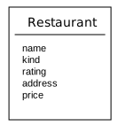
The UML diagram for the Restaurant class
The Restaurant class

The UML class diagram is a box that features a word, usually a noun, at the top of the box. This is the name of the class. There is a line and below the line, there is a list of attributes. In the  Restaurant  class, the attributes are things that we want to collect about each restaurant. If we were to turn the class diagram into a table, the attributes become the column titles:

namekindratingaddressprice
Holy CannoliItalian933 Sugo Streetexpensive
Rough BurgerBurger Joint422 Catsup Waycheap
Tacky HutSeafood311 Scale Roadvery cheap

To see this same concept with a different subject, here’s another table that lists friends and their possible attributes:

friendIDfirstNamelastNamehairColor
1FredStedblack
2FredMartinanull
3MartinaFredbrown
4FredRedblond
5FredRedblue

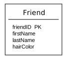
And here’s a class diagram that describes that same Friend table:

Mastery 07 – UML Part 2

State diagrams

A state diagram is used to represent the condition of the system or part of the system at finite instances of time. It’s a behavioral diagram and it represents the behavior using finite state transitions. State diagrams are also referred to as State machines and State-chart Diagrams. These terms are often used interchangeably. So simply, a state diagram is used to model the dynamic behavior of a class in response to time and changing external stimuli. We can say that each and every class has a state but we don’t model every class using State diagrams. We prefer to model the states with three or more states.

  1. Structure Diagrams – Used to model the static structure of a system, for example- class diagram, package diagram, object diagram, deployment diagram etc.
  2. Behavior diagram – Used to model the dynamic change in the system over time. They are used to model and construct the functionality of a system. So, a behavior diagram simply guides us through the functionality of the system using Use case diagrams, Interaction diagrams, Activity diagrams and State diagrams.

Package diagrams

Package diagram, a kind of structural diagram, shows the arrangement and organization of model elements in middle to large scale project. Package diagram can show both structure and dependencies between sub-systems or modules, showing different views of a system, for example, as multi-layered (aka multi-tiered) application – multi-layered application model.

Component diagrams

Component is something required to execute a stereotype function. Examples of stereotypes in components include executables, documents, database tables, files, and library files. Components are wired together by using an assembly connector to connect the required interface of one component with the provided interface of another component. This illustrates the service consumer – service provider relationship between the two components.

An assembly connector is a «connector between two components that defines that one component provides the services that another component requires. An assembly connector is a connector that is defined from a required interface or port to a provided interface or port.»[1]

When using a component diagram to show the internal structure of a component, the provided and required interfaces of the encompassing component can delegate to the corresponding interfaces of the contained components.

GRASP

General Responsibility Assignment Software Patterns (or Principles), abbreviated GRASP, consist of guidelines for assigning responsibility to classes and objects in object-oriented design. It is not related to the SOLID design principle.

The different patterns and principles used in GRASP are controller, creator, indirection, information expert, high cohesion, low coupling, polymorphism, protected variations, and pure fabrication. All these patterns answer some software problems, and these problems are common to almost every software development project. These techniques have not been invented to create new ways of working, but to better document and standardize old, tried-and-tested programming principles in object-oriented design.

Computer scientist Craig Larman states that «the critical design tool for software development is a mind well educated in design principles. It is not UML or any other technology.» Thus, GRASP are really a mental toolset, a learning aid to help in the design of object-oriented software.

MVC

MVC Pattern stands for Model-View-Controller Pattern. This pattern is used to separate application’s concerns.

Model – Model represents an object or JAVA POJO carrying data. It can also have logic to update controller if its data changes.

View – View represents the visualization of the data that model contains.

Controller – Controller acts on both model and view. It controls the data flow into model object and updates the view whenever data changes. It keeps view and model separate.

HFOOAD Chapter 5 – Flexible

Good Design= Flexible Software

For chapter five, most of what we learned has to do with what happens with software after you are done and you wanna mantain it or modify it, it clarifies that change is inevitable and we need to be prepared for it, if not, small changes can become big problems.

One strategy to do this is to generalize objects, make super classes, like a class instrument instead of guitar, which would let you expand to other instruments easily. This clases shoulb be abstarcr cause they are placeholders for the implementatio of actual instruments. This can be done everytime you find similar behaviors.

Mastery 06 – UML Part 1

UML is a standard language for specifying, visualizing, constructing, and documenting the artifacts of software systems. UML was created by the Object Management Group (OMG) and UML 1.0 specification draft was proposed to the OMG in January 1997. OMG is continuously making efforts to create a truly industry standard. UML stands for Unified Modeling Language. UML is different from the other common programming languages such as C++, Java, COBOL, etc.

UML is a pictorial language used to make software blueprints. UML can be described as a general purpose visual modeling language to visualize, specify, construct, and document software system. Although UML is generally used to model software systems, it is not limited within this boundary. It is also used to model non-software systems as well. For example, the process flow in a manufacturing unit, etc.

UML is not a programming language but tools can be used to generate code in various languages using UML diagrams. UML has a direct relation with object oriented analysis and design. After some standardization, UML has become an OMG standard.

Goals of UML
A picture is worth a thousand words, this idiom absolutely fits describing UML. Object-oriented concepts were introduced much earlier than UML. At that point of time, there were no standard methodologies to organize and consolidate the object-oriented development. It was then that UML came into picture. There are a number of goals for developing UML but the most important is to define some general purpose modeling language, which all modelers can use and it also needs to be made simple to understand and use.

UML diagrams are not only made for developers but also for business users, common people, and anybody interested to understand the system. The system can be a software or non-software system. Thus it must be clear that UML is not a development method rather it accompanies with processes to make it a successful system.

In conclusion, the goal of UML can be defined as a simple modeling mechanism to model all possible practical systems in today’s complex environment.

A Conceptual Model of UML
To understand the conceptual model of UML, first we need to clarify what is a conceptual model? and why a conceptual model is required? A conceptual model can be defined as a model which is made of concepts and their relationships. A conceptual model is the first step before drawing a UML diagram. It helps to understand the entities in the real world and how they interact with each other.

As UML describes the real-time systems, it is very important to make a conceptual model and then proceed gradually. The conceptual model of UML can be mastered by learning the following three major elements −

UML building blocks
Rules to connect the building blocks
Common mechanisms of UML
Object-Oriented Concepts
UML can be described as the successor of object-oriented (OO) analysis and design.

An object contains both data and methods that control the data. The data represents the state of the object. A class describes an object and they also form a hierarchy to model the real-world system. The hierarchy is represented as inheritance and the classes can also be associated in different ways as per the requirement.

Objects are the real-world entities that exist around us and the basic concepts such as abstraction, encapsulation, inheritance, and polymorphism all can be represented using UML.

UML is powerful enough to represent all the concepts that exist in object-oriented analysis and design. UML diagrams are representation of object-oriented concepts only. Thus, before learning UML, it becomes important to understand OO concept in detail.

Following are some fundamental concepts of the object-oriented world −

Objects − Objects represent an entity and the basic building block.

Class − Class is the blue print of an object.

Abstraction − Abstraction represents the behavior of an real world entity.

Encapsulation − Encapsulation is the mechanism of binding the data together and hiding them from the outside world.

Inheritance − Inheritance is the mechanism of making new classes from existing ones.

Polymorphism − It defines the mechanism to exists in different forms.

Mastery 05 – Design Patterns

Design patterns are a way general repeatable solution to a commonly occurring problem in software design. A design pattern isn’t a finished design that can be transformed directly into code. It is a description or template for how to solve a problem that can be used in many different situations.

Some examples are:

Creational design patterns

These design patterns are all about class instantiation. This pattern can be further divided into class-creation patterns and object-creational patterns. While class-creation patterns use inheritance effectively in the instantiation process, object-creation patterns use delegation effectively to get the job done.

Example of Abstract Factory
  • Abstract Factory
    Creates an instance of several families of classes
  • Builder
    Separates object construction from its representation
  • Factory Method
    Creates an instance of several derived classes
  • Object Pool
    Avoid expensive acquisition and release of resources by recycling objects that are no longer in use
  • Prototype
    A fully initialized instance to be copied or cloned
  • Singleton
    A class of which only a single instance can exist

Structural design patterns

These design patterns are all about Class and Object composition. Structural class-creation patterns use inheritance to compose interfaces. Structural object-patterns define ways to compose objects to obtain new functionality.

  • Adapter
    Match interfaces of different classes
  • Bridge
    Separates an object’s interface from its implementation
  • Composite
    A tree structure of simple and composite objects
  • Decorator
    Add responsibilities to objects dynamically
  • Facade
    A single class that represents an entire subsystem
  • Flyweight
    A fine-grained instance used for efficient sharing
  • Private Class Data
    Restricts accessor/mutator access
  • Proxy
    An object representing another object

Behavioral design patterns

These design patterns are all about Class’s objects communication. Behavioral patterns are those patterns that are most specifically concerned with communication between objects.